How to Design Connected Digital Thermometers Circuit Diagram 2.4 primary and secondary thermometers 2.5 calibration of thermometers 2.6 review of two kinds of conventional thermometers . chapter three. 3.0 methodology. 3.1 system block diagram 3.2 components of the system. 3.3 system circuit diagram. 3.4 system working principle

Circuit digram for Digital Thermometer using Arduino and LM35 Temperature Sensor , is shown in the above figure. Make the connections carefully as shown in the schematic. Here 16x2 LCD unit is directly connected to arduino in 4-bit mode. Data pins of LCD namely RS, EN, D4, D5, D6, D7 are connected to arduino digital pin number 7, 6, 5, 4, 3, 2.
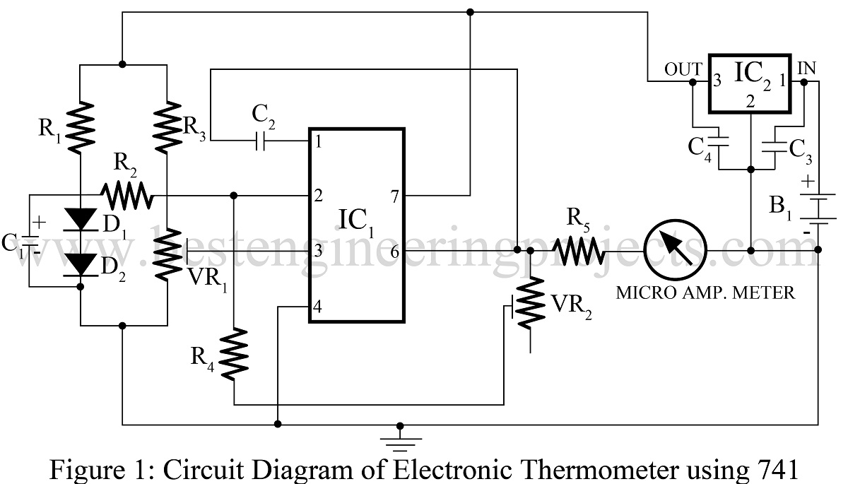
Diode Digital Thermometer Circuit Circuit Diagram
Make a Digital Thermometer: In this instructable, you will learn how to make a simple digital thermometer for under £10 using a few simple components and 1 IC. (I use hot glue just to secure the circuit board, switches, and thermistor in place)-Screwdriver (to adjust the potentiometers, unless you got the ones with knobs like mine, and to

Circuit Design of Digital Thermometer. LM35 is the temperature sensor used in this project. The output of the sensor is directly proportional to the temperature but in analogue form. Hence, the output of LM35 i.e. pin 2 is connected to analog input A0 of Arduino.
Digital Thermometer with Arduino & LM35 Temperature Sensor Circuit Diagram
Circuit diagram. Before we start building our digital thermometer, let's take a look at the circuit diagram: By following the circuit diagram, uploading the Arduino code, and building the circuit, you can create a fully functional digital thermometer that displays temperature values in Celsius and Fahrenheit. Whether you are a beginner or LM35DZ is capable of reading the temperature in Centigrade scale. The output voltage of the sensor is directly proportional to the temperature in centigrade. LM35 can be used in the range of -55°C to +150°C with +/- 0.75°C accuracy. So let's learn how to design a Digital Thermometer Using Arduino & LM35 Temperature Sensor. The entire circuit works off a 9V battery. Assemble the circuit on a general-purpose PCB and enclose in a small plastic box. Calibrate the thermometer using presets VR1 and VR2. After calibration, keep the box in the vicinity of the object whose temperature is to be measured. Sent by Mihail Dorutz, CH. Thanks a lot! Digital Thermometer Circuit