Microgrid energy management and monitoring systems A Circuit Diagram Adeel Asad IOT Based Power Monitoring System for Smart Grid Applications Year of Publication: February 2020. Microcontroller: The project is based on a pre-programmed ATmega micro controller. The complete system divided in four sections. Analog sensor interfacing, analog to digital converter (ADC), wireless Here, we will be monitoring the output voltage, current, and power of the panel using the ESP32 IoT development board. Choosing the Right Components for IoT Enabled Solar Power Monitor. With a solar monitor, it becomes very easy to monitor and detect faults in any solar system. This is why component selection becomes a very important part when
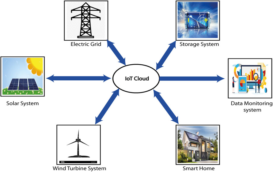
time to time. This proposed system utilizes an Arduino microcontroller. The unit which is generated can be displayed on the webpage through the Wi-Fi module. Smart grid is one of the features of smart city model. It is energy consumption monitoring and management system. Smart grids are based on communication between the

PDF Development of Automated Grid Monitoring and Control System ... Circuit Diagram
Kumar"An IoT Based Smart Energy Management System",2018, ICCCA. [8] Somnath Saha, Tushar Tyagi, Dhananjay V. Gadre, "ARM® Microcontroller based Automatic Power Factor Monitoring and Control System", 2013 Texas Instruments India Educators' Conference. [9] Himanshu Singh, Vishal Pallagani, Vedant Khandelwal and Venkanna U, software and the hardware components of the system. It is the brain of the monitoring system. Hence, it functions to enable the monitoring capabilities of the system. The PIC microcontroller used for this project has been programmed by a software code written by the MikroC language, with the MikroC PRO for PIC compiler. The PIC microcontroller
Technology Relays Relays, RTACS + Grid connect library Project Funding any Independent power producers or Utilities Customer Examples Entergy Utilties ‐ XM (Columbia) Southern companies, Also Energy, New York Power Authority with Tesla batteries Approximate Project Cost $5K $20K Approximate Project Size < 10MW <100MW
PDF Power Grid Control Using Arduino Circuit Diagram
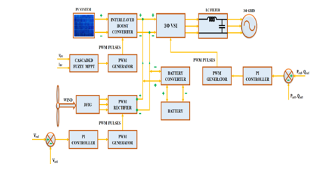
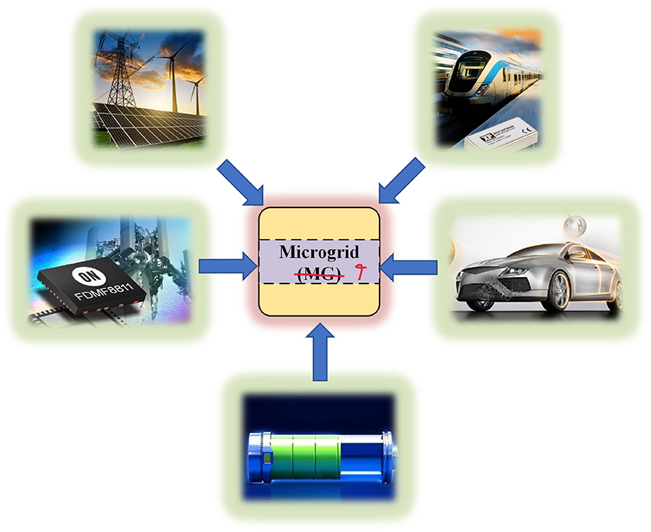
monitoring system. The grid can be controlled and managed using the results of processing in which some of the control tasks can be either automated or manually operated. Smart grid generally refers to a highly integrated power-based grid having the capability of distinguishing the different types of powers such as wind power, solar power

power grid system design and operation. The smart power grid includes a sensing, monitoring, and control system that provides end-users with real-time energy cost pricing. Furthermore, smart metering's sophisticated control systems allow energy customers to react quickly to real-time pricing. It safeguards the connected