Voltage Regulator Circuit Circuit Diagram Learn how to create a simple voltage regulator circuit using a schematic diagram. Understand the different types of voltage regulators, their components, and how they work to maintain a constant output voltage. Learn how to maintain a constant output voltage level with a voltage regulator circuit diagram. Explore the basic components, functions, and types of voltage regulators, including linear, switching, and programmable regulators.
Components of an Automatic Voltage Regulator Circuit. An automatic voltage regulator circuit consists of several key components that work together to regulate and stabilize the output voltage. These components include: Transformer: The transformer is a key component in the automatic voltage regulator circuit. It is responsible for stepping down
LM317 Adjustable voltage regulator Circuit Diagram
The LM317 voltage regulator circuit requires only two external resistors to set the output voltage. If a fixed resistor is connected between the output and adjustment pin, it can also be a precision current regulator. Fig 5 : Internal circuit diagram of LM317 with labelled functional blocks. Startup circuit.
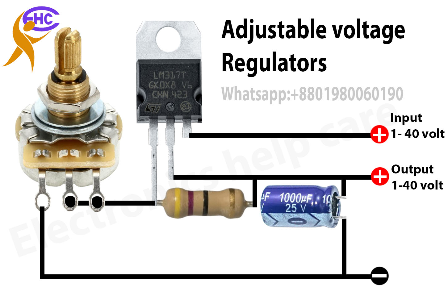
The Basic Circuit Diagram of The LM317 or KA317 Voltage Regulator. If the distance between the IC regulator and input is too large. We should put Ci to reduce the noise. Other than this, if you want a high-efficiency output. LM317 Voltage Regulator Example Circuits. We learn enough about LM317. Let's take a look at it in action, hope you

How to Build an Automatic Voltage Regulator Circuit: A Complete Diagram ... Circuit Diagram
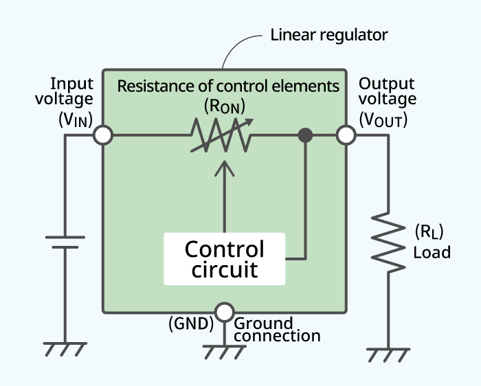
Learn about voltage regulators, electronic circuits that maintain a constant voltage level. Explore the different types of linear and switching regulators, their circuits and how they work.

The voltage regulator used in Figure 4 is often called a three terminal fixed voltage regulator. Common output regulated voltages can be 5, 6, 8, 12, 15, 18, 24 volts, etc. (Various current ratings are also available from manufacturers.) Figure 4. Basic voltage regulator circuit diagram. Figure 5. Schematic and connection diagrams for voltage